Hi guys, It's been a long time since my last post. Actually I was busy in making my smartwatch project. Guess what I have already interfaced and written the drivers for the RTC, Display, IMU. And I have successfully created a clock displaying date and time on the display. I will guide you on how to build this smartwatch yourself through a series of blog post. So keep watching and happy learning.
For now I have only these few stuffs. I will keep on adding features as I continue building it.The SMART Things
So let's get started. First I will let you know what all things I am using for this smartwatch. Here is a list along with the link where you can get these things cheapest in India. For outsiders I think Sparkfun, Adafruit, eBay, Amazon etc will be good place to search for.
Getting CCS
- Getting CCS for your Tiva C Launchpad is simple.
- Just click on the link provided above.
- Click on "Get Software" button beside SW-EK-TM4C123GXL. This is the entire software package including the drivers required to program your device.
- Register for a myTI account and fill up the required details.
- You will get a download link. Download software.
- Extract the file. From EK-TM4C123GXL-CCS-786\Tools\CCS\CCS5.4.0.00091_win32 run ccs_setup_5.4.0.00091.exe (It will take a while..... around 45 minutes)
- Install only the components required or the entire thing if you are not worried about the space required.
- Now from EK-TM4C123GXL-CCS-786\TivaWare install SW-EK-TM4C123GXL-2.1.0.12573.exe
- A tip: Try to install the software in the default directory coz CCS installations can often be nasty.
- Check out this pdf if you are facing any problem installing.
The CLOCK is Ticking!!
Lets start with the RTC. DS1307 is a really popular and really efficient Real Time Clock. It can be accessed and controlled by I2C protocol. It is a good practice to study the datasheet first if you are working with a device from scratch. It gives you the freedom to develop your own drivers for the device. You can check out the datasheet here. You can find the register addresses of the device in the datasheet. You only need to concentrate on that portion.


If you are a total noob like me and you are working with I2C for the first time then this is a good place to start. You don't need to know each and every details of I2C, only an overview will be sufficient since we will be using the peripheral drivers provided in the Tivaware software package provided by TI.
The Brain
You may ask "Hey why the hell are you not using Arduino ?". I will answer "Hey why don't you go and play with the kids". Oh come on, the world has seen a lot of arduino. Let's try something different. Let's create a device from scratch. Let's not hide behind the abstractions of arduino, lets dig in and see how things work from inside out. So controversies apart lets talk about the microcontroller that we are going to use. It is an ARM Cortex M4 controller by Texas Instrument and it is named TM4CGH6PM. Based on this controller they built a development board called the Tiva C Launchpad to make our job easier. It has I2C, SSI, UART and a whole lot of processing power that will be more than enough for our smart watch.
 | ||||
| Tiva C Launchpad Pin Out |
Setting up Code Composer Studio (CCS)
This is a very tricky part. Since CCS is based on the Eclipse IDE it is a bit tricky to get things to work the first time. But don't worry because TI has provided some example projects for us to get things started easily.
- Open CCS and follow the steps in this pdf.
- If you are not in a mood to read the pdf just go to Project->Import Existing CCS Eclipse Project
- Click on "Select search-directory" and browse to C:\ti\TivaWare_C_Series-2.1.0.12573\examples\boards\ek-tm4c123gxl or the drive where you have installed.
- Click "Select all" and then Finish.


Now you are ready to do all the coding stuff.
Wire it UP
Now that you have got your softwares ready let's wire up the circuit. The connections are with respect to the pinout diagram given above. Sorry I didn't get a Fritzing part for this board.
Let's get your hands Dirty
Copy the following code in your blank C file.
//include files
 #include <stdarg.h>
 #include <stdbool.h>
 #include <stdint.h>
 #include "inc/hw_i2c.h"
 #include "inc/hw_memmap.h"
 #include "inc/hw_types.h"
 #include "inc/hw_gpio.h"
 #include "driverlib/i2c.h"
 #include "driverlib/sysctl.h"
 #include "driverlib/gpio.h"
 #include "driverlib/pin_map.h"
 #include "driverlib/uart.h"
 #include "utils/uartstdio.h"
 //Defines for DS1307
 #define SLAVE_ADDRESS 0x68
 #define SEC 0x00
 #define MIN 0x01
 #define HRS 0x02
 #define DAY 0x03
 #define DATE 0x04
 #define MONTH 0x05
 #define YEAR 0x06
 #define CNTRL 0x07
 //initialize I2C module 0
 //Slightly modified version of TI's example code
 void InitI2C0(void)
 {
   //enable I2C module 0
   SysCtlPeripheralEnable(SYSCTL_PERIPH_I2C0);
   //reset module
   SysCtlPeripheralReset(SYSCTL_PERIPH_I2C0);
   //enable GPIO peripheral that contains I2C 0
   SysCtlPeripheralEnable(SYSCTL_PERIPH_GPIOB);
   // Configure the pin muxing for I2C0 functions on port B2 and B3.
   GPIOPinConfigure(GPIO_PB2_I2C0SCL);
   GPIOPinConfigure(GPIO_PB3_I2C0SDA);
   //GPIOPadConfigSet(GPIO_PORTB_BASE, GPIO_PIN_2, GPIO_STRENGTH_2MA, GPIO_PIN_TYPE_OD);
   //GPIOPadConfigSet(GPIO_PORTB_BASE, GPIO_PIN_3, GPIO_STRENGTH_2MA, GPIO_PIN_TYPE_OD);
   //GPIODirModeSet(GPIO_PORTB_BASE, GPIO_PIN_2, GPIO_DIR_MODE_HW);
   //GPIODirModeSet(GPIO_PORTB_BASE, GPIO_PIN_3, GPIO_DIR_MODE_HW);
   // Select the I2C function for these pins.
   GPIOPinTypeI2CSCL(GPIO_PORTB_BASE, GPIO_PIN_2);
   GPIOPinTypeI2C(GPIO_PORTB_BASE, GPIO_PIN_3);
   // Enable and initialize the I2C0 master module. Use the system clock for
   // the I2C0 module. The last parameter sets the I2C data transfer rate.
   // If false the data rate is set to 100kbps and if true the data rate will
   // be set to 400kbps.
   I2CMasterInitExpClk(I2C0_BASE, SysCtlClockGet(), false);
   //clear I2C FIFOs
   HWREG(I2C0_BASE + I2C_O_FIFOCTL) = 80008000;
 }
 //sends an I2C command to the specified slave
 void I2CSend(uint8_t slave_addr, uint8_t num_of_args, ...)
 {
   // Tell the master module what address it will place on the bus when
   // communicating with the slave.
   I2CMasterSlaveAddrSet(I2C0_BASE, slave_addr, false);
   //stores list of variable number of arguments
   va_list vargs;
   //specifies the va_list to "open" and the last fixed argument
   //so vargs knows where to start looking
   va_start(vargs, num_of_args);
   //put data to be sent into FIFO
   I2CMasterDataPut(I2C0_BASE, va_arg(vargs, uint32_t));
   //if there is only one argument, we only need to use the
   //single send I2C function
   if(num_of_args == 1)
   {
     //Initiate send of data from the MCU
     I2CMasterControl(I2C0_BASE, I2C_MASTER_CMD_SINGLE_SEND);
     // Wait until MCU is done transferring.
     while(I2CMasterBusy(I2C0_BASE));
     //"close" variable argument list
     va_end(vargs);
   }
   //otherwise, we start transmission of multiple bytes on the
   //I2C bus
   else
   {
     //Initiate send of data from the MCU
     I2CMasterControl(I2C0_BASE, I2C_MASTER_CMD_BURST_SEND_START);
     // Wait until MCU is done transferring.
     while(I2CMasterBusy(I2C0_BASE));
     //send num_of_args-2 pieces of data, using the
     //BURST_SEND_CONT command of the I2C module
     unsigned char i;
     for(i = 1; i < (num_of_args - 1); i++)
     {
       //put next piece of data into I2C FIFO
       I2CMasterDataPut(I2C0_BASE, va_arg(vargs, uint32_t));
       //send next data that was just placed into FIFO
       I2CMasterControl(I2C0_BASE, I2C_MASTER_CMD_BURST_SEND_CONT);
       // Wait until MCU is done transferring.
       while(I2CMasterBusy(I2C0_BASE));
     }
     //put last piece of data into I2C FIFO
     I2CMasterDataPut(I2C0_BASE, va_arg(vargs, uint32_t));
     //send next data that was just placed into FIFO
     I2CMasterControl(I2C0_BASE, I2C_MASTER_CMD_BURST_SEND_FINISH);
     // Wait until MCU is done transferring.
     while(I2CMasterBusy(I2C0_BASE));
     //"close" variable args list
     va_end(vargs);
   }
 }
 //read specified register on slave device
 uint32_t I2CReceive(uint32_t slave_addr, uint8_t reg)
 {
   //specify that we are writing (a register address) to the
   //slave device
   I2CMasterSlaveAddrSet(I2C0_BASE, slave_addr, false);
   //specify register to be read
   I2CMasterDataPut(I2C0_BASE, reg);
   //send control byte and register address byte to slave device
   I2CMasterControl(I2C0_BASE, I2C_MASTER_CMD_BURST_SEND_START);
   //wait for MCU to finish transaction
   while(I2CMasterBusy(I2C0_BASE));
   //specify that we are going to read from slave device
   I2CMasterSlaveAddrSet(I2C0_BASE, slave_addr, true);
   //send control byte and read from the register we
   //specified
   I2CMasterControl(I2C0_BASE, I2C_MASTER_CMD_SINGLE_RECEIVE);
   //wait for MCU to finish transaction
   while(I2CMasterBusy(I2C0_BASE));
   //return data pulled from the specified register
   return I2CMasterDataGet(I2C0_BASE);
 }
 unsigned char dec2bcd(unsigned char val)
 {
      return (((val / 10) << 4) | (val % 10));
 }
 // convert BCD to binary
 unsigned char bcd2dec(unsigned char val)
 {
  return (((val & 0xF0) >> 4) * 10) + (val & 0x0F);
 }
 //Set Time
 void SetTimeDate(unsigned char sec, unsigned char min, unsigned char hour,unsigned char day, unsigned char date, unsigned char month,unsigned char year)
 {
      I2CSend(SLAVE_ADDRESS,8,SEC,dec2bcd(sec),dec2bcd(min),dec2bcd(hour),dec2bcd(day),dec2bcd(date),dec2bcd(month),dec2bcd(year));
 }
 /*/Set Date
 void SetDate(unsigned char day, unsigned char date, unsigned char month,unsigned char year)
 {
      I2CSend(SLAVE_ADDRESS,9,0x00,DAY,dec2bcd(day),DATE,dec2bcd(date),MONTH,dec2bcd(month),YEAR,dec2bcd(year));
 }*/
 //Get Time and Date
 unsigned char GetClock(unsigned char reg)
 {
      unsigned char clockData = I2CReceive(SLAVE_ADDRESS,reg);
      return bcd2dec(clockData);
 }
 void ConfigureUART(void)
 {
   //
   // Enable the GPIO Peripheral used by the UART.
   //
   SysCtlPeripheralEnable(SYSCTL_PERIPH_GPIOA);
   //
   // Enable UART0
   //
   SysCtlPeripheralEnable(SYSCTL_PERIPH_UART0);
   //
   // Configure GPIO Pins for UART mode.
   //
   GPIOPinConfigure(GPIO_PA0_U0RX);
   GPIOPinConfigure(GPIO_PA1_U0TX);
   GPIOPinTypeUART(GPIO_PORTA_BASE, GPIO_PIN_0 | GPIO_PIN_1);
   //
   // Use the internal 16MHz oscillator as the UART clock source.
   //
   UARTClockSourceSet(UART0_BASE, UART_CLOCK_PIOSC);
   //
   // Initialize the UART for console I/O.
   //
   UARTStdioConfig(0, 115200, 16000000);
 }
 void main(void)
 {
      // Set the clocking to run directly from the external crystal/oscillator.
        SysCtlClockSet(SYSCTL_SYSDIV_4 | SYSCTL_USE_PLL | SYSCTL_OSC_INT | SYSCTL_XTAL_16MHZ);
        //initialize I2C module 0
        InitI2C0();
        ConfigureUART();
        SetTimeDate(30,32,8,4,5,11,14);
        unsigned char sec,min,hour,day,date,month,year;
        while(1)
        {
             sec = GetClock(SEC);
             min = GetClock(MIN);
             hour = GetClock(HRS);
             day = GetClock(DAY);
             date = GetClock(DATE);
             month = GetClock(MONTH);
             year = GetClock(YEAR);
             SysCtlDelay(SysCtlClockGet()/10*3);
             UARTprintf("%02d:%02d:%02d \n%02d %02d/%02d/%02d\n",hour,min,sec,day,date,month,year);
        }
} - Enable the peripheral
- Reset the peripheral
- Enable the GPIO with which the peripheral is multiplexed.
- Configure the GPIO to use those peripheral pins.
- Configure GPIO pin type.
- Initialize the peripheral.
The Peripheral Driver Library User Manual would be the right place to know about the APIs. TI has also provided some pretty good examples to get started. If you want to build a product from scratch you have to do the hard work guys. Believe me this may sound a bit complicated to you but I had no idea about these things a week back. I studied all the datasheets and the user manuals and some blogs in the TI community to get started and then things started to flow.
Reading datasheets is a very good habit if you want to take control of the product that you are building.
What's the TIME bro ??
Now that you have understood how the RTC works and written your first code. It is time to chr=eck out the time.
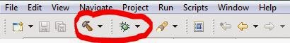
- Now click on the little hammer(build) icon on the top of the CCS window. This will build and compile your program and check for errors. Hopefully you wont have any errors if you have followed my steps.
- Now that your code is error free click on the little bug(debug) icon beside the hammer icon.
- This will take you to the debug screen where you can dump your code to the controller and debug all the variables, registers etc.

- Now obviously you would like to check the time. So go on and open up a serial monitor like Putty and open the serial port to which your controller is connected and set it to baud rate 115200 and click open.
- You can check which COM port your device is connected by right-clicking on Computer click on Manage and go to Device Manage. Under Device Manager click on the triangle beside Ports to see which COM port your controller is connected.

- You can see a window like this showing the time every one second.

So go on and tweak the program according to your own need and display time in your own format. You can also dispaly names of the day and month instead of just numbers.
Happy coding and keep watching my blog for more updates on smartwatch.
P.S. - Next we will work with Nokia 5110 LCD to display time there. Excited??
Very nice :)
ReplyDeleteHi Mark,
DeleteThank you
Sounak,
ReplyDeleteI have a problem, I can't read or even alter the Master Data Register @ address 0x4002 0008
Hope you can shed light.
Thanks,
hello sir .... i have found four error while building my project in the code composer studio.the errors are following
ReplyDelete1.#10010 errors encountered during linking
2.#10234-d unresolved symbols remain
3.unresolved symbols uartstudioconfig, first referenced in
the only way to not encounter those problem is to make your own library. I did make my own library by reading the reference manual
ReplyDeletehow i make my own library sir.....
DeleteIt is safe to say that you are searching for paid applications for nothing? How might you complete it? Here is it: Appvn Download for PC. Appvn Download for PC will help you to download applications, eBooks, diversions, ringtones, funnies, backdrops, music, screensavers, and so on. All these stuff can be downloaded for nothing. Appvn Download for PC can be effortlessly dealt with by everybody. You can search for various applications that suit your decision. You can download Appvn for PC on Windows 10, Windows 8, Windows 7 or Windows XP for utilizing the premium applications for nothing.
ReplyDeleteAws online training in india
ReplyDeleteSalesforce online training in india
SAS Online Training in india
Salesforce admin online training in india
Linux Online
training in India
I got what you mean , thanks for posting .Woh I am happy to find this website through google.
ReplyDeletegood smartwatches
Wow, very nice blog. I like it. thanks for sharing helpful post.
ReplyDeleteEmbedded Systems Course in Gurgaon
thanks for share the information your blog and also check it appvn apk
ReplyDeleteAjio Promo Codes
ReplyDeleteAjio Coupons & Offers
Ajio Coupon codes
Ajio Offers Promo Codes
Ajio Offers on online shopping
Firstcry Promo Codes
Firstcry Deals & offers
Firstcry coupons codes
Firstcry Coupons Offers Promo Codes
Firstcry Offers on Kids shopping
Myntra promo codes
Myntra deals and offers
Myntra coupon codes
Myntra coupons offers promo codes
Myntra offers on online shopping
Nykaa Promo Codes
Nykaa Deals and offers
Nykaa Coupons codes
Nykaa coupons offers promo codes
Nykaa offers on online shopping
ReplyDeleteFlipkart promo codes
Flipkart deals & coupons
flipkart coupon code
flipkart coupons offer promo code
Amazon promo code
amazon offers
amazon offers and deals
amazon coupon code
amazon deal of the day
cleartrip promo codes
cleartrip coupon code
cleartrip offers and deals
cleartrip deals
MMT promo Codes
MMT coupon codes
Makemytrip promo codes
makemytrip offers
makemytrip deals & offers
healthkart coupon code
Cloud Computing Training In Noida
ReplyDeleteWebtrackker is IT based company in many countries. Webtrackker will provide you a real time projects based training on Cloud Computing. If you are looking for the Cloud computing training in Noida then you can join the webtrackker technology.
Cloud Computing Training In Noida , Cloud Computing Training center In Noida , Cloud Computing Training institute In Noida ,
Company Address:
Webtrackker Technology
C- 67, Sector- 63, Noida
Email: info@webtrackker.com
Website: www.webtrackker.com
http://webtrackker.com/Cloud-Computing-Training-Institutes-In-Noida.php
Video editing course in Noida
ReplyDeleteVideo editing training institute in Noida- Webtrackker Technology is and IT Training institute providing the Video editing course in Noida, FCP, Final Cut Pro Training in Noida. For more call us- 8802820025.
Video editing course in Noida
best video editig course in noida
best video edtitng institute in noida
Company Address:
Webtrackker Technology
C- 67, Sector- 63, Noida
Phone: 01204330760, 8802820025
Email: info@webtrackker.com
Website: http://webtrackker.com/Best-training-institute-Video-editing-FCP-course-in-Noida.php
This comment has been removed by the author.
ReplyDeletethank you your post was knowlable to me
ReplyDeleterpa training institute in noida
sas training institute in noida
hadoop training institute in noida
blokchain traninig institut noida
Such an informative blog that i have red yet.I hope the data you gave is helpful for the students.i have read it very interesting information's.
ReplyDeleteDOT NET Training in Chennai
Big Data Training in Chennai
Hadoop Training in Chennai
Android Training in Chennai
German Classes in Chennai
Digital Marketing Course in Chennai
JAVA Training in Chennai
Selenium Training in Chennai
Selenium Training Institute in Chennai
Selenium Training in Annanagar
article is really nice and it is related with video downloaders. yes you can install tubemate app easily in your mobile or your pc. tubemate is now available to download your iPhone too. download tubemate 2018 apk latest file using below link.
ReplyDeletehttps://www.tubematedownloader.net
Are you looking for Distance Learning Courses in India most of the students choose and apply, Talentedgenex there are many popular courses which attract the students for having distance education. For more info visit this site:- Distance learning courses in India ,
ReplyDeleteTalentedgenext Way of Online Learning, Distance Education, is an increasing number of becoming popular all over the world due as it has many benefits. For further details visit in this site:- Distance Education Website,
ReplyDeleteStudents who are willing to work and peruse education at the same time Distance education BBA/Business management and marketing management is the best option! For more info, visit-
ReplyDeleteDistance Education BBA,
"Thanks for sharing informative information with us. it is really helpful for my ahead career.
ReplyDeleteDigital Marketing Training Course in Chennai | Digital Marketing Training Course in Anna Nagar | Digital Marketing Training Course in OMR | Digital Marketing Training Course in Porur | Digital Marketing Training Course in Tambaram | Digital Marketing Training Course in Velachery
"
This is great, thanks for sharing it. Also, check this out if you are looking for professional website or logo design services:
ReplyDeleteBuy Logo
Amazing!
ReplyDeleteSuch a wonderful and helpful blog for me.
Thank you for sharing it with us.
Buy Law Essay UK
Hey, I read your blog. It's very helpful for me and such a very unique blog thanks for sharing it with us. If you want the best law assignment Help Uk then visit our site with a 7O% discount. I expect you will be satisfied with our service.
ReplyDelete